描述
技術規格
1.減速馬達規格: 5V,減速比1:48
2.車子 長x寬(包括輪子): 20cm x 18.5cm。
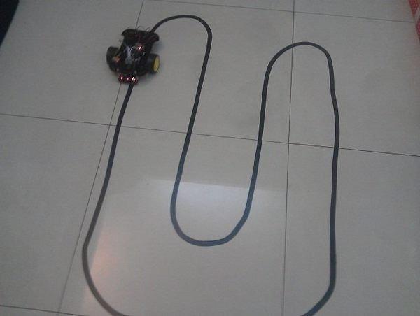
3. 3路紅外線循線感測模組:利用紅外光探測,抗幹擾能力強,採用CTRT5000傳感器,工作電壓 5V,白線輸出低電壓。
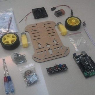
商品內容
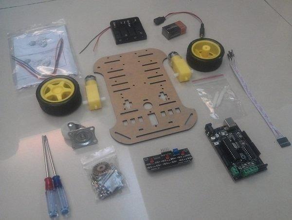
1. Motoduino 電路板一片(相容於Arduino Duemilanove)
2. 十字及一字螺絲起子各一支
3. 車體 (兩個輪胎及減速馬達,一個舵輪等)
4. 6 pin排線一條 (含3-pin長排針 x 2)
5. 紅外線循線感測器一個
6. 一條 USB 傳輸線
7. 塑膠六角柱(2x長, 2x短, 2x螺帽)
8. 2顆18650電池盒
套件內未含電池
程式範例
///三路紅外線感測器與Motoduino的腳位對應
// 如果是用 Motoduino U1 則使用如下
const int SLeftLeft = 9; //左感測器輸入腳
const int SMiddle = 8; //中間感測器輸入腳
const int SRightRight = 7; //右感測器輸入腳
// 馬達與motoduino的腳位對應
// 如果是用 Motoduino U1 則
const int Motor_E2 = 6; // 控制馬達2轉速 digital pin 6 of Arduino (PWM)
const int Motor_E1 = 5; // 控制馬達1轉速 digital pin 5 of Arduino (PWM)
const int Motor_M1 = 10; // 控制馬達1正反轉 digital pin 10 of Arduino
const int Motor_M2 = 11; // 控制馬達2正反轉 digital pin 11 of Arduino
// 感測器狀態值
byte byteSensorStatus=0;
void setup() {
//set up serial communications
Serial.begin(57600);
// 輸出入接腳初始設定
pinMode(SLeftLeft, INPUT);
pinMode(SMiddle, INPUT);
pinMode(SRightRight, INPUT);
pinMode(Motor_M1, OUTPUT); // 設定 Motor_M1為輸出腳位
pinMode(Motor_M2, OUTPUT); // 設定 Motor_M2為輸出腳位
}
//////////// 主程式 ////////
void loop(){
int nIRStatus;
//清除感測器狀態值
byteSensorStatus = 0;
// 讀取左感測器狀態值
nIRStatus = digitalRead(SLeftLeft);
if(nIRStatus == 1)
byteSensorStatus = (byteSensorStatus | (0x01 << 2));
// 讀取中間感測器狀態值
nIRStatus = digitalRead(SMiddle);
if(nIRStatus == 1)
byteSensorStatus = (byteSensorStatus | (0x01 << 1));
// 讀取右邊感測器狀態值
nIRStatus = digitalRead(SRightRight);
if(nIRStatus == 1)
byteSensorStatus = (byteSensorStatus | 0x01);
drivemotor(byteSensorStatus);
}
///////////////////////////
void drivemotor(byte nStatus)
{
switch(nStatus)
{ // 感測器 黑色:1 白色:0
case 7: // SL:1 SM:1 SR:1 //黑黑黑
motorstop(0, 0);
break;
case 6: // SL:1 SM:1 SR:0 //黑黑白
left(0, 255);
break;
case 5: // SL:1 SM:0 SR:1 //黑白黑
motorstop(0, 255);
break;
case 4: // SL:1 SM:0 SR:0 //黑白白
left(0, 255);
break;
case 3: // SL:0 SM:1 SR:1 // 白黑黑
right(0, 255);
break;
case 2: // SL:0 SM:1 SR:0 // 白黑白
forward(0, 255);
break;
case 1: // SL:0 SM:0 SR:1 // 白白黑
right(0, 255);
break;
case 0: // SL:0 SM:0 SR:0 //白白白
forward(0, 255);
}
}
void motorstop(byte flag, byte motorspeed)
{
Serial.println(“停止!”);
digitalWrite( Motor_E1, motorspeed);
digitalWrite( Motor_E2, motorspeed);
}
void forward(byte flag, byte motorspeed)
{
Serial.println(“forward!”);
digitalWrite( Motor_M1, HIGH);
digitalWrite( Motor_M2, HIGH);
analogWrite( Motor_E1, motorspeed);
analogWrite( Motor_E2, motorspeed);
}
void backward(byte flag, byte motorspeed)
{
Serial.println(“backward!”);
digitalWrite( Motor_M1, LOW);
digitalWrite( Motor_M2, LOW);
analogWrite( Motor_E1, motorspeed);
analogWrite( Motor_E2, motorspeed);
}
void right(byte flag, byte motorspeed)
{
Serial.println(“right!”);
digitalWrite( Motor_M1, HIGH);
digitalWrite( Motor_M2, HIGH);
analogWrite( Motor_E1, 0);
analogWrite( Motor_E2, motorspeed);
}
void left(byte flag, byte motorspeed)
{
Serial.println(“left!”);
digitalWrite( Motor_M1, HIGH);
digitalWrite( Motor_M2, HIGH);
analogWrite( Motor_E1, motorspeed);
analogWrite( Motor_E2, 0);
}
////////////////////////////////////////////////////
部落格參考: http://sinocgtchen.blogspot.com/2013/05/motoduinoarduino-l293d-ir-tracker-sensor.html
影片觀賞: http://www.youtube.com/watch?v=sTala_3r8mA&list=UU6aKpj71jLKYABYLr3Wbpuw&index=13
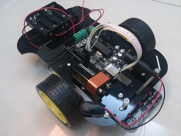
接線範例
組裝完成圖。


